


Free energy permanent magnet generator: Induction motor is also a generator - invention of Charles Flynn
These types of videos garner many views, and comments opposing them are often deleted.
Many videos on YouTube show real free energy technology, but the technology inside is hidden, meaning the electronic circuitry is concealed.
Similar versions can include one generator head and two induction motors or two generator heads with two induction motors, converted by flywheel gear ratios.
The essence of these machines can be reduced to a single induction motor, which also functions as a generator.
This article introduces such a free energy engine, which is both a motor and generator, invented by Charles Flynn.
A brushless induction motor and an AC generator have quite similar structures, consisting of two main components: a coil (armature) and a permanent magnet (inductor). See picture:

If you understand how to generate electricity based on a magnet rotating around an axis, then I'll tell you the main problem.
On the rotor, attach two magnets symmetrically on the disc (as shown). The inductor contains many coils; in the picture above, there are seven coils.
It is clear that as the magnet rotates, it goes through several stages and passes through the coils one after the other. As the magnet begins to pass through the center of the coil, the voltage essentially reaches its maximum. At this time, an induced electromotive force is generated in the coil that opposes the moving magnet. This force is also called Lenz's force in the generator, which is deduced from Faraday's law of electromagnetic induction.
The phase voltage at one end of the wire is usually a sine wave but can have other shapes depending on the magnet placement and the way the wire is wound. I use the example of a sine wave to describe the evolution of a voltage phase at one end of each coil:

Describe the specific relationship between the generator in question and the output voltage phase:

As the magnet begins to pass through the center point of the coil, it passes through the axis, which is a line perpendicular to the plane containing the coil. This line passes through the center of gravity of the coil. At that time, the voltage reaches its maximum, and the reverse electromotive force of the coil acting on the magnet is the largest.
The question is: How to remove this jet?
Solution: interrupt the current with electronic components when voltage is applied to the closed circuit and the voltage reaches its maximum.
Interrupting with electronic components is equivalent to suddenly opening the circuit. Breaking this circuit creates a voltage called Vq. See drawing:

To create that sudden circuit breaker, we have the following circuit by Charles Flynn. This circuit shows how to extract the two outputs of the coil, enter the closed circuit, and make the circuit suddenly cut off using NPN transistors and N-channel FET transistors.
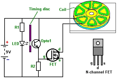
The battery has a voltage of 9V, which actually keeps the LED light on. When the perforated rotating disk passes, the light goes through the hole and reaches the phototransistor, closing the circuit.
It is the voltage Vq in the graph above that causes the magnet, which should be prevented, to be pushed with a force stronger than the initial force. This causes the disk attached to the magnet to be pushed and accelerated to a certain speed.

Notice the figure above: The free energy set when the area of the KDVqR domain is larger than the area of the ODK domain. Then, this circuit has an output power greater than the input power due to starting..
The disc should have slowed down, but thanks to the electronic circuit, it sped up.
As a result, the 9V battery is recharged, and the disc accelerates to a very high speed.
See the entire Charles Flynn engine design reconstructed by experts: Permanent Magnet Motor: Charles Flynn's Free Energy Magnetic Generator
Details about the electronic components (N-channel MOSFET, phototransistor, etc.) responsible for closing and cutting the circuit:
Only five components are used. The current through the coil is controlled by a transistor, specifically a Field-Effect Transistor (FET). The most common type of FET used is an N-channel FET, which is roughly equivalent to an NPN transistor. An N-channel FET is switched off when the voltage on its "gate" (marked "g" in the diagram) is 2.5 volts or lower. It is switched on when the voltage on its gate is 4.5 volts or more.
In this circuit, we want the FET to switch on when the motor's timing disc is in the correct position and be off at all other times. This is arranged by shining the light from a Light-Emitting Diode (LED) through a hole in the timing disc, which rotates with the shaft of the motor. When the hole is opposite the LED for the coil that is to be powered up, light shines through the hole and onto a light-sensitive device. Charles has chosen to use a light-sensitive transistor, but a light-dependent resistor such as an ORP12 could be used instead. When the light shines on the "Opto1" device in the circuit diagram, its resistance falls dramatically, raising the voltage on the gate of the FET and switching it on. When the timing disc hole moves past the LED, the light is cut off, and the FET gate voltage drops, switching the FET off. This arrangement causes the coil of the motor to be switched on and off at just the right time to provide powerful rotation of the motor shaft. In the circuit, the resistor "R1" ensures that the current flowing through the LED is not excessive. The resistor "R2" has a low value compared to the resistance of "Opto1" when no light falls on it, holding the gate voltage of the FET down to a low value and ensuring the FET is completely off.
Enhance the exploitation of Free Energy
Charles Flynn's published free energy generator does not provide guidance on developing and enhancing the optimal exploitation of free energy. Perhaps the appendix documents for the invention were lost (due to repression?).
But essentially, the design with the electronic circuit diagram for exploiting the back EMF of the motor to charge the battery, as presented above, is sufficient to prove that free energy exists, even though the 9V batteries are not a large reserve.
This is the circuit I devised to exploit voltage transients to charge the battery:

According to the diagram above, the diode will block the current with too large a voltage from entering the LED lamp operating at a voltage of 9V. The battery bank only receives current due to the discharge of high-voltage pulses.
The inverter will convert direct current (DC) voltage into alternating current (AC). The output from the inverter will supply power to the house.
Additional devices:
Battery: You can choose an old, almost broken battery bank to create a dipole, as the battery bank will continuously be charged as the engine rotates. The battery now acts as a dipole to maintain voltage. However, using a new battery is better. See: Battery (You should use Acid batteries to avoid fire and explosion)
Inverter: Based on the house's electricity usage, choose a high or low-capacity inverter. See: Inverter
See more necessary electrical equipment here: Electrical Devices by EASY POWER PLAN
Comments - Conclusion
To create a generator, also an induction motor of this type by Charles Flynn, you need to see the technical presentation reconstructed by a free energy expert. See the article "Permanent Magnet Motor: Charles Flynn's Free Energy Magnetic Generator."
Several companies have developed Charles Flynn's invention, creating high-power generators that sell for thousands of dollars. Developing this technology requires an understanding of Ether field physics.
This motor is also a generator, and it can be converted to a form without a rotating device. This is based on electronic components that generate high-frequency pulses to replace rotating discs with switching photodiodes.
If you want to create a generator for energy independence or to reduce your electricity bill, take a look at the blueprint with the following summary:
Revealed At Last... Must watch!
Free Energy Magnetic Generator and synthesizes many other technologies imbued with Nikola Tesla's technological identity
✔ Nikola Tesla’s method of magnifying electric power by neutralizing the magnetic counter-forces in an electric generator
~Generates Energy-On-Demand~: 👉 Free Energy Will Change Our World Forever
✔ Combination of induction motor and alternator
✔ Combine generators with induction motors - self-powered generators with rotary motion
✔ ~Various methods of generating high power immobile generators~
✔ Or maybe called Overunity for the system. Mother Nature doesn't care about people calling or naming phenomena. Overunity/Free Energy, Zero Point Energy (ZPE) are just a few different words
Although Charles Flynn's generator was simple, creating a disc with a magnet as a base and punching holes can be difficult for someone without a lathe or chisel. With the design I mentioned above, you can choose to buy equipment and components available at stores, and then assemble it according to the instructions.


