CERTIFICATION OF ORIGINALITY
This is to certify I am responsible for the work submitted in this project, that the
original work is my own except as specified in the references and
acknowledgements, and that the original work contained herein have not been
undertaken or done by unspecified sources or persons.
Bi Toroid transformer is invented for obtaining efficiency beyond 100%. The
structure of a Bi Toroid transformer is different from a Conventional transformer
because it has one primary coil and two secondary coils. It is designed using two
different cores, material wise and size wise. The secondary core is designed to be
less reluctance than the primary core. This is done by using larger and higher relative
permeability for the secondary core. This will ensure that the secondary core is less
reluctance than the primary core. Thus, the induced EMF will not couple back to the
primary side. This will ensure that secondary coils induced EMF will follow the less
reluctance path. This will boost the efficiency of the transformer past the 100% mark.
1. INTRODUCTION
1.1 Background
Transformer is an electrical device that transfers energy from a device to another
through electromagnetic induction. Electromagnetic induction can cause losses and
make efficiency rate lesser (typical transformer efficiency – 90% to 99%).[1] The
lesser the efficiency more energy lost occurs
 |
| Figure 1 Conventional Transformer pulse movements |
When a pulse of input power is delivered to Coil 1 (Primary coil), it creates a
magnetic wave which passes though Coil 2 (Secondary winding) and back to Coil1
again as shown by the blue arrows. This magnetic pulse generates an electrical
output in Coil 2, which flows through the electrical load providing it with the power
which it needs to operate.
The pulse in Coil 2 also generates a magnetic pulse, and unfortunately, it runs in the
opposite direction, opposing the operation of Coil 1 and causing it to have to boost
its input power in order to overcome this backward magnetic flow, apart from losses occurred during the operation. So, this is what makes electrical efficiency of a
conventional transformer will always be less than 100%
 |
| Figure 2 Bi Toroid Transformer Pulse Movements |
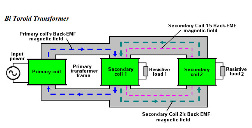
Bi Toroid Transformer is designed and invented by a Canadian Inventor, Mr.
Thane Heins (Patent No: CA2594905A1). It consists of one primary coil and
two secondary coils. Primary core and Secondary core made from different
materials and differs in size. Secondary core is designed to be less reluctant.
So, the return pulse takes a much easier path which does not lead back to Coil
1 at all since secondary coil is made of less reluctant core. This boosts the
efficiency of the transformer. The inventor also claimed that the device has
been able to generate electricity. Thus, the efficiency has go beyond 100%.
1.2 Problem Statement
This device has been patented and claimed to generate electricity because the
efficiency is higher than 100%. If the device is really capable of generating
electricity, it can be used to address energy scarcity problem. However, not much
have been understood and reviewed of the source of the additional energy produced
by the device, I.e. where the extra energy coming from? How it is possible to
achieve the efficiency above 100% and what are the limitations of the device?
1.3 Objectives
- To design, test and analyze a Bi – Toroid transformer using ANSYS software.
- To understand how it works by using ANSYS software
1.4 Scope of Study
- More focus given on the materials used to design the transformer and the
windings.
- Experiments will be carried out to understand how this device work by using
ANSYS software
1.5 Relevance and Feasibility
The study conducted based on transformers, the materials used and the effects of it
on efficiency of the transformer and how to improve it. In addition, the valuation and
the suitable factor to increase the efficiency are done based on past research papers
and experiments conducted.
2. LITERATURE REVIEW
2.1 Conventional Transformer
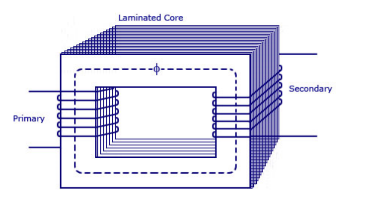
A conventional transformer is a device that has two or more coils of wire physically
wrapped around the laminated core. They consists mainly two cores, primary and
secondary. The primary is connected to an ac power source and the secondary is
open circuited
 |
| Figure 3 Conventional Transformer |
Operating Principle: The operating principal of the transformer is based on Faraday‟s Law. There are 2
laws of Faraday, first law states that any changes that happened in a magnetic field of
a coil of wire will cause an electromagnetic field (emf) to be induced in the coil. As
for the second law of Faraday, it is stated that the magnitude of electromagnetic field (emf) induced in the coil is equal to the rate of change of flux that linkages with the
coil.[2] The induced voltage is given by,
{e_{ind}} = N\frac{{d\overline \Phi }}{t} (1)
where Φ¯¯¯¯ is the average flux per turn in a coil and N is is the number of turns in the
coil. Therefore,
\overline \Phi = \frac{\lambda }{N} (2)
where 𝜆 is the flux linkage in the coil across where the voltage is being induced, and
it is the sum of the flux passing through each turn in the coil added. Thus,
\lambda = \sum\limits_{i = 1}^N {{\Phi _i}} (3)
Transformer works using the principle of Faraday‟s law where it uses
electromagnetic induction of two coils, the primary and secondary coils. When there
is a current change occurs in primary side, the secondary side also will have changes
in current. Subsequently, EMF induced in the secondary coil due to Faraday‟s Law
of Electromagnetic induction.[2] Basically, transformers are based on two principles
- Magnetic field (electromagnetism) can be produced by an electric current.
- Voltage induced in the end of the coil (electromagnetic induction) by
changing magnetic field within a coil of wire
So, as a result, the induced voltage in each winding depends on the number of turns
in that winding.
Losses in a conventional transformer that have to be taken into account [3]:
1. Copper / I2R losses are the resistive heating losses in the primary and
secondary windings of the transformer[3].
2. Eddy current losses are the losses due to resistive heating in the core of the
transformer[3].
3. Iron / Hysteresis losses are due to lagging of the magnetic molecules within
the core because of the alternating magnetic flux and it is associated with the
rearrangement of the magnetic domains in the core during each half cycle[3].
4. Leakage fluxes are the fluxes that escape the core and only pass through one
windings of the transformer[3].
The force of power loss in a transformer decides its efficiency. The efficiency of a
transformer is reflected in power (wattage) loss between the primary and secondary
windings. At that point the resulting efficiency of a transformer is equivalent to the
proportion of the power ratio of the secondary winding, to the power input of the
primary winding, and is thus high.
Due to this problem (losses), the efficiency of a transformer is always below 100%,
typical efficiency of a conventional transformer is 91%-99%.[4][1] Efficiency of a
transformer can be calculated as:
{\rm{efficience, \eta = }}\frac{{Output{\rm{ }} power}}{{Input{\rm{ }} power}} (4)
2.2 Bi Toroid Transformer
Bi Toroid Transformer is a special transformer that has developed by a Canadian
Inventor, Thane Heins (patent no: CA2594905A1). It differs with a conventional
transformer in terms of number of coils and number of cores. A Bi Toroid
transformer has on primary coil and two secondary coils whereas a conventional
transformer only has one primary coil and one secondary coil.
 |
| Figure 4 Bi Toroid Transformer |
Operating Principle
A Bi Toroid transformer is designed to have one primary side and two secondary
sides. Apart from that, it has two different cores in terms of size and materials. The
secondary core is bigger in size and as for material; it has higher permeability
material than the primary side. This will ensure that the secondary core will have
much lesser reluctance than the primary core, thus, the pulse generated from the core
wont couple back. By doing this, the efficiency will increase dramatically.
 |
| Figure 5 Bi Toroid Operating Principle |
A common transformer has an efficiency around (91-99) % depending on the various issues[5]. Apart from that, it only has one primary side and one secondary side. As for a Bi-Toroid transformer, the efficiency can go up to 100% or more and it has one primary coil and two secondary coils. The secondary cores have lower reluctance than the primary core. By doing this, the electromagnetic fields (EMF) will not couple back with the primary core because of the higher reluctance flux path[1]. So, the desired output on no-load will be achieved as same as the input with near no load power factor.[6]
As for the reluctance, it can be adjusted by using different cores or by just using
different sizes for the primary side and the secondary side. The bigger the size, the
lower the reluctance. The other way is to use different cores for primary and
secondary sides. This can be done by using higher reluctance core for example iron
with lower permeability on the primary side and using permalloy which has high
permeability and lower reluctance on the secondary sides.[1][7]
 |
| Figure 6: Bi Toroid Transformers |
2.3 Materials used for the cores
One of the main criteria in order to design a Bi-Toroid transformer is by using
different materials. Other than using different materials, different sizes of cores can
be applied to design the Bi-Toroid transformers but it would not be as effective as
using different types of materials as the different permeability of the cores will be
more efficient than different sizes of the same cores. [1]
The primary core consist of normal transformer iron core which has permeability
around 200 while the secondary cores consists of permalloy which has permeability
around 100 000[1][7]. Permalloy is made of roughly 80% Nickel and 20% iron so
that makes it reluctance low. [8]. Permeability can be calculated as below,
Permeability(µ) = Flux Density(B) x Magnetizing Force(H) (5)
 |
| Figure 7: Permeability Graph |
 |
| Figure 8: Hysteresis Loop (Iron VS Permalloy) |
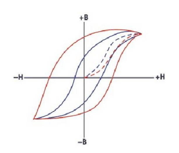
Iron has the wider hysteresis loop, that means it has higher reluctance and lower
permeability as for Pemalloy, it has narrower loop, that means it has lower reluctance
and higher permeability.[9]
2.4 Power Factor (PF)
Power factor (pf) is the ratio of the real power (W) and apparent power (VA). The
power factor will be in the range of 0-1. When the power is reactive power (usually
inductive load), the power factor will be „0‟ while, when the power is real power
(resistive load), the power factor will be‟1‟.[10]
𝑷𝑭 = 𝑷(𝐖) / |𝑺(𝐕𝐀)| (7)
PF = Power Factor
P = Real Power (w)
S = Apparent Power (VA)
For sinusoidal current, the power factor PF is equal to the absolute value of the
cosine of the apparent power phase angle φ
𝑷𝑭 = 𝐜𝐨𝐬 𝝋 (8)
PF = Power Factor
cos𝜑 = Apparent power phase angle
 |
Figure 9 Power Factor Graph
Phase angle φ = 90⁰, so, cos 90 = 0. That means no real power consumed and purely
reactive power consumed. So, this will make the real power = 0.
Figure 10 Power Factor Graph 2
Phase angle φ = 0⁰, so, cos 0 = 1. That means no reactive power consumed and
purely real power consumed.
2.5 Testing/ExperimentsThere are several experiments and testing conducted by Thane Heins in order to
proof that a bi toroid transformer can achieve efficiency above 100%. Below are the
experiment conducted.
Power Factor (pf) testing/experiment
Figure 11: Bi Toroid Sine Waves
Voltage and Current 90 degrees apart, so pf=0 |
Figure 12: Conventional Transformer Sine Waves
Voltage and Curent in phase, so pf=1
The power factor(pf) for Bi-Toroid transformer must be „0‟ or nearly „0‟ since it
consumes reactive power and not real power as a conventional transformer does and
that‟s the reason of the power factor (pf)=1.[11]
Efficiency Test (Conventional Transformer)
Figure 13 Conventional Transformer Efficiency Test
Input Voltage = 9.8 Volts
Input Current = 0.393 Amps
Power Factor = 0.95 / 18 degrees
Load = 10 Ohms
Load Voltage = 5.21 Volts
Load Power = 2.71 Watts
Input Power = 3.66 Watts
Efficiency = 74 %
Efficiency Test (Bi Toroid Transformer)
 |
| Figure 14 Bi Toroid Transformer Efficiency Test |
Input Voltage = 122.3 Volts
Input Current = 0.061 Amps
Power Factor = 0.021 / 78 degrees
Load = 10 Ohms
Load Voltage = 5.23 Volts
Load Power = 2.74 Watts
Input
Power = 1.55 Watts
Efficiency = 177 %
3. METHODOLOGY
For this project, more studies will be done on the past research about the Bi-Toroid
transformers. The materials used to design the core and the windings will be the main
edge. Apart from that the experiments and tests involved to determine the efficiency
of the transformer also will be vital
3.1 Tools and Software
ANSYS software will be used to design and simulate the Bi-Toroid transformer.
From the software, the design (prototype) will be analyzed. The main analysis on the
prototype is the efficiency rate of the transformer with the respect of losses. All these
analysis will be conducted using ANSYS software.
3.2 Flow Chart
Figure 15 Flow Chart
At the early stage of the project, studies will be done on the Bi Toroid and the
conventional transformers. The research is conducted to acquire better understanding
on the subject through literature reviews, journals reading, and internet research. The
right materials and windings studied in order to design a Bi Toroid transformer. Once
the transformer is designed with a proper design, the vital part occurs, experiments
and testing. All the required tests and experiments should be carried out in order to
obtain the desired results. All these experiments and results will be obtained by using
ANSYS software. Once the result obtained, the final model for pre sedex should be
done by optimizing the model and a draft report should be completed. The
hardbound submission is the end of the process once dissertation and viva are done.
3.3 No Load Test
Conventional Transformer and Bi Toroid transformer are placed on No Load and the
output observed and the readings will be taken using oscilloscope and multimeters.
Figure 16 No Load Test
3.4 On Load Test
Both the Bi Toroid Transformer and the Conventional Transformer will be placed on
Load and the output observed and reading will be taken.
Figure 17 On Load Test
3.5 Gantt Chart
Table 1 Gantt Chart
 |
| Key Milestone |
4. DESIGN OF THE TRANSFORMER CORE (AutoCAD)

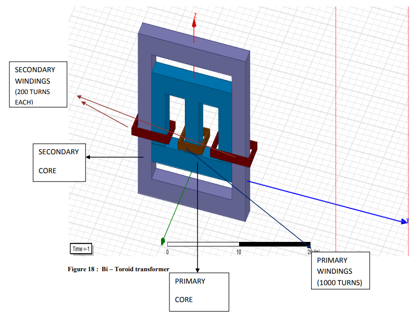
This is the proposed design of the Bi Toroid transformer. It consists of two different
cores with different materials respectively. The primary core is made of silicon steel
whereas the secondary coil is made of permalloy. The size of the secondary core is
twice the size of the primary core; this is due to reluctance, the secondary core is less
reluctant than the primary core.
3D ANSYS SOFTWARE DESIGN
Bi – Toroid Transformer
Conventional Transformer
5. RESULTS AND FINDINGS
BP & BH curves
Figure 20 : BH & BP Curves
Power Factor Testing (Bi-Toroid)
Figure 21 PF graph (Bi-Toroid)
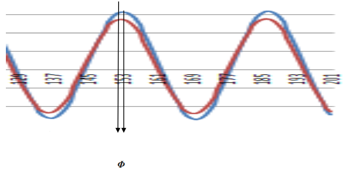
The current and voltage are not in phase, almost 90⁰ apart. So the pf is small, nearly
0. So it consumes reactive power to supply real power.
Power Factor Testing (Conventional)
Figure 22 PF graph (Conventional)
The current and voltage are in phase, so, the pf is nearly 1. It consumes real power to
supply real power.
Efficiency Calculations
Bi Toroid Calculations
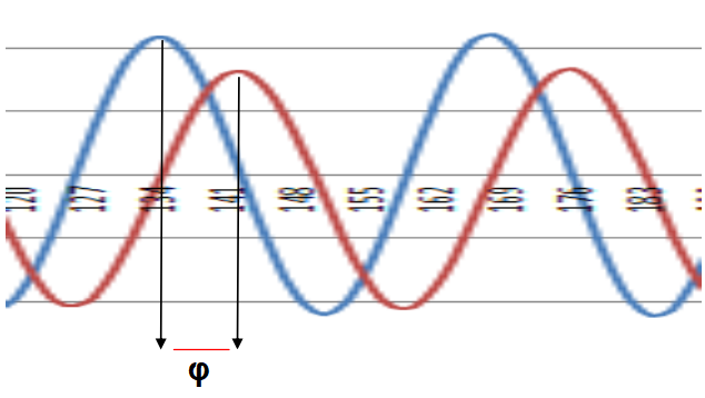 |
| Figure 23 PF (Bi - Toroid |
From the above graphs, it shows that the current and voltage for a Bi-Toroid
transformer are almost 90⁰ apart on the primary side. This means:
PF = cos φ
= cos 85⁰
= 0.087
So, the power factor for the Bi-Toroid transformer is nearly "0".
 |
| Figure 24 Voltages ( Bi - Toroid) |
The above graph shows the input/output voltages of the Bi – Toroid transformer. The
input voltage is 240 V while the output voltage is 105 V.
 |
| Figure 25 Currents (Bi- Toroid) |
The above graph shows the input/output currents of the Bi – Toroid transformer. The
input current is 0.1 A while the output current is 0.38 A.
Power Calculations
𝑷 = 𝑽𝑷 × 𝑰𝑷 × 𝐜𝐨𝐬 𝝋 (9)
Input Power
P = 240 x 0.1 x 0.087
= 2.088 W
Output Power
P = 105 x 0.3829 x 0.087
= 3.497 W
Efficiency
𝑃 = 3.497
2.088 × 100
= 168 %
Conventional Calculations
From the primary side, the output waveform shows that the current and voltage are in
phase and it‟s almost 0⁰ apart.
PF = cos φ
= cos 15⁰
= 0.96
So, the power factor for the Conventional transformer is nearly „1‟.
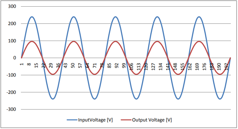 |
| Figure 27 Voltages (Conventional) |
The above graph shows the input/output voltages of the Conventional transformer.
The input voltage is 240 V while the output voltage is 96 V.
 |
| Figure 28 Currents (Conventional) |
The above graph shows the input/output currents of the Conventional transformer.
The input current is 0.1 A while the output current is 0.25 A.
- Input Power
P = 240 x 0.1 x 0.96
= 23.04 W
- Output Power
P = 96 x 0.2450 x 0.96
= 22.5792 W
Efficiency
𝑃 = 22.5792
23.04 × 100
= 98 %
Calculations (Simplified)
Table 2 Data Gathered:
Table above is the simplified version of the parameters obtained via ANSYS
software. The input voltages and the input current injected for both the transformers
are the same, 240 V and 0.1 A respectively. The output voltage acquired for
Conventional transformer is 96 V while the output voltage obtained for Bi-Toroid
transformer is 105 V. As for current, Conventional transformer showed output
current of 0.245 A while the Bi-Toroid transformer showed 0.3826 A. Both
transformers obtained less core losses, 560mW and 750mW respectively.
Table 3 Power & Efficiency
Table above shows the efficiency rate of both Conventional transformer and Bi –
Toroid transformer. Efficiency rate for the conventional transformer is 98% while the
efficiency rate for the Bi – Toroid transformer is 168%. It proves that Bi – Toroid
transformer can achieve efficiency beyond 100%.
5. CONCLUSION AND RECOMMENDATION
As a conclusion, a proper study regarding a Bi Toroid transformer should be carefully conducted because the Bi-Toroid transformer can achieve its 100% or more efficiency if the correct methods followed. The choosing of the materials depending on its permeability and reluctance, the different sizes of the cores, secondary core must be larger than the primary core, as well as the number of turns involved in primary side and two secondary coils are vital in order to achieve the desired objectives.
Permalloy used as the material for the secondary core. It is chosen because of its high
permeability and very low reluctance properties. Since, there are less availability of
this materials possibly due to its usage, it is hard to conduct a proper research or
studies in this materials in person. So, it is recommended that different materials like
this would be made available for students to enhance or develop something new.
Apart from that, in this modern world, technologies are developing to be on par with
the living standards that improving from time to time. Portable electronics product
plays a vital part in today‟s generation such as mobile phones, cameras and ipads.
Sadly, all these products use a rechargeable battery that means, it will drain out of
charges with use. The more you use, the faster it will run out of power[12].
In order to counter this problem, portable power bank discovered. It can charge a
device up to four times depending on the size of the battery. But, there is a minus
point with portable power bank. It will supply power according to its size that means
it has limitations. A 7500mAh power bank can supply up to its maximum capacity
which is 7500mAh only and have to be recharged in order to perform again.
A Bi Toroid transformer can be used in developing a power bank. Since its efficiency
is more than 100%, it just needed to be charged once. The transformer will supply
extra voltage and the extra voltage can be used to automatically recharge the power
bank without being recharged manually. It can be used forever without being worried
about the capacity of the power bank.
 |
| Figure 29 Application of Bi Toroid Transformer |
The studies and research conducted above are one of the preliminary assessments.
The design and modeling in ANSYS is just to prove that the Bi – Toroid transformer
can achieve the objective which is to obtain efficiency beyond 100 %. Hence can
harvest its own energy. This is not possible without the prototype. So, the prototype
must be fabricated to make sure the theoretical results obtained through simulation
are no fluke.
Revealed At Last: Ancient Invention Generates Energy-On-Demand
✔ Nikola Tesla’s method of magnifying electric power by neutralizing the magnetic counter-forces in an electric generator
✔ Combination of induction motor and alternator
✔ Combine generators with induction motors - self-powered generators with rotary motion
✔ Various methods of generating high power immobile generators
✔ Or maybe called Overunity for the system. Mother Nature doesn't care about people calling or naming phenomena. Overunity or Free Energy, or Zero Point Energy (ZPE) are just a few different wordsAlso See: Ether Technology




.png)
